
- inCAD Library Home
- > No.000138 Tray Pulling Mechanism
No.000138 Tray Pulling Mechanism
12
12
The T-shaped hook eliminates the necessity of a chuck.
Related Category


Precision Linear Shafts
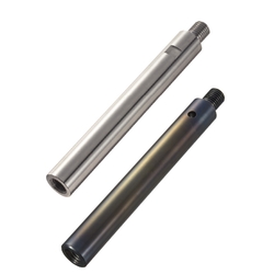
| Product name | One End Threaded/One End Tapped with Cross-Drilled Hole/Wrench Flats |
|---|---|
| Part number | SFAZ20-193-F15-B10-P12-N6-SC50 |
| Features | Selectable from 2 Types: Precision Type and Standard Type. |
* Orange colored cells in the table below indicate the part numbers used in this example.
Selection criteria
The shaft is used because it has a pilot on one side.
Available sizes
■Shafts (Standard, with wrench flats)
| Material | Hardness | Surface Treatment |
|---|---|---|
| EN 1.3505 Equiv. | High Frequency Hardening, Effective Hardening Depth 58HRC- EN 1.4125 Equiv. 56HRC- | - |
| EN 1.4125 Equiv. | ||
| EN 1.3505 Equiv. | Hard Chrome Plating: Plating Hardness 750 HV - Plating thickness 5μ or more | |
| EN 1.4125 Equiv. | ||
| EN 1.3505 Equiv. | Low Temp. Black Chrome Plating | |
| EN 1.1191 Equiv. | - | Hard Chrome Plating Plating Hardness 750 HV - Plating Thickness 5 µm or more |
| EN 1.4301 Equiv. |
■Sizes and Dimensions
| O.D. Tolerance Type | O.D. (mm) | Length (Configure in 1 mm increment) |
|---|---|---|
| g6 h5 f8 | 6 | 25-598 |
| 8 | 25-798 | |
| 10 | 25-798 | |
| 12 | 25-998 | |
| 13 | 25-998 | |
| 15 | 25-998 | |
| 16 | 25-1198 | |
| 18 | 25-1198 | |
| 20 | 25-1198 | |
| 25 | 25-1198 | |
| 30 | 25-1498 | |
| 35 | 25-1498 | |
| 40 | 40-1498 | |
| 50 | 50-1498 |
Accuracy Info.
■Shaft Accuracy Information
| O.D. Tolerance | |||
|---|---|---|---|
| O.D. (mm) | g6 | h5 | f8 |
| 6 | -0.004 -0.012 | 0 -0.005 | -0.010 -0.028 |
| 8 | -0.005 -0.014 | 0 -0.006 | -0.013 -0.035 |
| 10 | |||
| 12 | -0.006 -0.017 | 0 -0.008 | -0.016 -0.043 |
| 13 | |||
| 15 | |||
| 16 | |||
| 18 | |||
| 20 | -0.007 -0.020 | 0 -0.009 | -0.020 -0.053 |
| 25 | |||
| 30 | |||
| 35 | -0.009 -0.025 | 0 -0.011 | -0.025 -0.064 |
| 40 | |||
| 50 | |||

Stopper Bolts With Bumpers
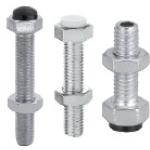
| Product name | Stopper Bolts with Bumpers/Standard/Straight Shape |
|---|---|
| Part number | UST5-20 |
* Orange colored cells in the table below indicate the part numbers used in this example.
Selection criteria
Selected a stopper with urethane to absorb the shock
Available sizes
■Stopper bolts (shouldered standard)
| Stopper | Bolt | Accessory(Hex nut) | ||||
|---|---|---|---|---|---|---|
| Material | Hardness | Material | Strength Class | Surface Treatment | Material | Surface Treatment |
| Urethane (Black) | Shore A90 | EN 1.7220 Equiv. | 10.9 | Bright Chromate Plating | EN 1.0038 Equiv. | Trivalent Chromate |
| EN 1.4301 Equiv. | - | - | EN 1.4567 Equiv. | - | ||
| Low Repulsion Urethane (Gray) | Shore A70 | EN 1.7220 Equiv. | 10.9 | Bright Chromate Plating | EN 1.0038 Equiv. | Trivalent Chromate |
| Polyacetal (White) | - | EN 1.7220 Equiv. | 10.9 | Bright Chromate Plating | EN 1.0038 Equiv. | Trivalent Chromate |
| EN 1.4301 Equiv. | - | - | EN 1.4567 Equiv. | - | ||
| Silicon (Light Gray) | Shore A70 | EN 1.7220 Equiv. | 10.9 | Bright Chromate Plating | EN 1.0038 Equiv. | Trivalent Chromate |
| EN 1.4301 Equiv. | - | - | EN 1.4567 Equiv. | - | ||
■Sizes and Dimensions
| Screw Dia.(Coarse) | Threaded section length (Length under head) |
|---|---|
| M3 | 15 - 40 (Increments of 5) |
| M4 | 15 - 40 (Increments of 5) |
| M5 | 15 - 50 (Increments of 5) |
| M6 | 20 - 50 (Increments of 5), 60 |
| M8 | 20 - 50 (Increments of 5), 60 |
| M10 | 20 - 50 (Increments of 5), 60, 70 |
| M12 | 30 - 70 (Increments of 10) |


-
 Terms of use of CAD data and simplified drawing data
- These terms and conditions (hereinafter referred to as “the Terms") set forth the conditions for downloading CAD data and simplified drawing data provided by MISUMI Corporation (hereinafter referred to as "MISUMI") via www.misumi-europe.com operated by MISUMI Europa GmbH(hereinafter referred to as the "Website"). By downloading CAD data and simplified drawing data posted on the Website (hereafter referred to as “Data”), customers are deemed to have agreed to these Terms.
- 1. Purpose of Use
-
MISUMI offers the following:
1)CAD data found on the Website (3D CAD data, 3D Intermediate data and 2D CAD data) for the purpose of informing customers of the characteristics of the products offered by MISUMI or a manufacturer affiliated with MISUMI for use in their designs.
2)Simplified drawing data (in PDF format) for the purpose of checking the specifications of products. - 2. Characteristics of Data
- There may be a discrepancy in certain characteristics of products (for example: tolerance, surface roughness, chamfer, etc.) between the Data and the actual product. Furthermore, for the purpose of reducing the file size of the Data, some information such as oil groove shapes, threads, or spring shapes, may be removed from the Data.
- 3. Disclaimer
- MISUMI carefully creates the Data but makes no warranty as to the quality, accuracy, functionality, safety, reliability, etc., of the Data. MISUMI may at any time, and with no prior notice to customers, revise or delete Data. MISUMI assumes no responsibility for any damage or loss resulting from any revision or deletion of the Data, or any errors in said data. Customers are solely responsible for all aspects of their own designs, including those made using the Data. MISUMI may provide customers with design example data on the Website, but the quality, accuracy, functionality, safety, reliability, etc., of such data are not guaranteed. MISUMI may, at any time, and in its sole discretion, request that the customer cease its use of or destroy the Data in its possession. MISUMI may request the customer provide MISUMI documentation of such destruction.
- 4.Prohibited Acts
-
Customers or users of the Data, are prohibited from the following acts regarding the Data, in whole or in part:
(1)Requesting quotations or placing orders for products with third parties other than those authorized by MISUMI or its affiliates;
(2)Receiving quotations or orders for products from third parties by providing the Data to a third party or using the Data in their own business;
(3)Displaying links to the Website related to the Data on their own websites, etc., without consent of MISUMI or its affiliates;
(4)Using or reproducing the Data beyond the scope of the above-stated Purpose of Use;
(5)Modifying, altering, tampering with, translating, or adapting the Data;
(6)Selling, transferring, lending, sublicensing, or providing the Data to third parties in any way without consent of MISUMI or its affiliates;
(7)Altering the content, reverse engineering, decompiling, disassembling, or analyzing the Data;
(8)Publicly disclosing or exhibiting the Data without consent of MISUMI or its affiliates;
(9)Using the Data for the purpose of providing products and services identical or similar to those of MISUMI or its affiliates;
(10)Performing acts that interfere with the proper functioning of this Website, such as acquiring Data in bulk. - 5. Copyright
-
All title and copyright in and to any information contained in the Data are owned by MISUMI or the relevant manufacturer affiliated with MISUMI and are protected by applicable copyright laws and international treaties. By downloading Data, the customer acquires no ownership rights of any kind in the intellectual property contained within. Without prior approval from MISUMI, no part of the Data may be utilized (reproduced, modified, reverse-engineered, uploaded, presented, sent, distributed, licensed, sold, or published) for any purpose other than that mentioned above.
In the event Data is found to have been to be used for any purpose other than that mentioned above or against any applicable laws or the Terms, MISUMI may pursue any legal remedy available to it, which may result in forbidding the offending user from using the Data or accessing the Website. - 6. Third-Party Data
- MISUMI offers some Data provided by third parties. Such Data may be subject to separate terms and conditions, in addition to these terms. MISUMI makes no guarantee or warranty regarding Data from third parties.
- 7. Export Control
- Customers shall comply with all applicable laws and regulations regarding the export of the Data.
- 8. Amendments to the Terms
- MISUMI may, at any time, and in its sole discretion, modify these terms and conditions; any such modification will be effective immediately.
- 9. Severability
- If any term or provision of these Terms is invalid, illegal, or unenforceable in any jurisdiction, such invalidity, illegality, or unenforceability shall not affect any other term or provision of these Terms or invalidate or render unenforceable such term or provision in any other jurisdiction. Section 139 BGB (German Civil Code) shall not apply.
- 10.Miscellaneous
-
In the event that Customers violate the Terms, MISUMI and/or MISUMI Europa GmbH shall be entitled to claim the damages and expenses (including attorney's fees) incurred by such violation against the Customers.
These Terms and any disputes arising in connection therewith shall be exclusively governed by and construed in accordance with the laws of the Federal Republic of Germany, without regard to its conflicts of law principles. The courts located in Frankfurt am Main/Germany shall have exclusive jurisdiction to adjudicate any dispute arising in connection with these Terms. By downloading the Data, you agree to submit to the exclusive and personal jurisdiction of the courts located in Frankfurt am Main/Germany. - Revised: September 21, 2025
CAD Data Download (Unit Assembly)
CAD Data Download: File Format
Cautions on the CAD data
-
Assembly data shows the assembly drawings in the concept design phase. The sole purpose of the data is to explain the structure and functionality of the assembly and is not considered nor to be used as a final design.
You will need to edit the Data so that it meets your specific design conditions. -
The CAD data unit assembly consists of sub-assemblies.
Each sub-assembly unit can be used as it is or can be edited. - The Data for fabricated parts is based on easy-to-edit dimensions and shapes in sketches and histories.
- The Data including the third-part components are made by the Company.
* The part in the frame is a sub-assembly unit.
-

- * Unit assembly CAD data consists of some sub-assemblies.
Each sub-assembly unit can be used as it is or can be edited.
Application Overview
Purpose
- A simple one axis mechanism to pull and return an ascending/descending tray driven by a pneumatic linear guide.
Points for use
- Automatic horizontal movement achieved by pneumatically-driven linear guides
Target workpiece
- Workpiece: resin tray
outer dimensions: W268 x D173 x H17
workpiece weight: 1.5kg
Design Specifications
Operating Conditions or Design Requirements
- Cylinder Stroke: 380 mm
- Outer dimensions: W520 x D240 x H205
Required Performance
- Overall transfer weight: 6.2 N
Selection Criteria for Main Components
- Pneumatically-driven linear guides
- Pneumatically-driven linear guides with a stroke of 380 mm or longer are selected.
Design Evaluation
Verification of main components
- Whether the pneumatically-driven linear guides have the required output power for pulling the tray.
- Pneumatically-driven linear guides
- Pressure area:113 mm ²
- Operating pressure: 0.4 MPa
- Theoretical output: (pressure area) x (operating pressure) = 113 x 0.4 = 45.2 N
- Overall transfer weight: m = (chuck weight) + (workpiece weight) = 1.5 + 14.7 = 15.2 N
- Friction coefficient: k = 0.4
- F = mk = 15.2 x 0.4 = 6.1N < 45.2N(OK)
Other Design Consideration
- By using a T-shaped hook instead of a chuck, the mechanism is more simple and efficient.
- This unit operates by inserting the T-shaped hook in the workpiece through an ascending/descending lift unit.
- Assemble the device with the shafts (pilots) for the mounting board set as the datum for device position.
- Shafts are adopted because circular posts do not have a pilot on one side.
- Another stopper not equipped with a cylinder is used in the case where the workpiece is displaced due to inertia. This also prevents the cylinder thrust from being directly applied to the T-shaped groove, and protects the resin tray.
Explore Similar Application Examples
Page
-
/
-


Payment Method


On-Demand Manufacturing
Certificates


Copyright © MISUMI Corporation All Rights Reserved.