
- inCAD Library Home
- > No.000225 Roller Cleaning Mechanism
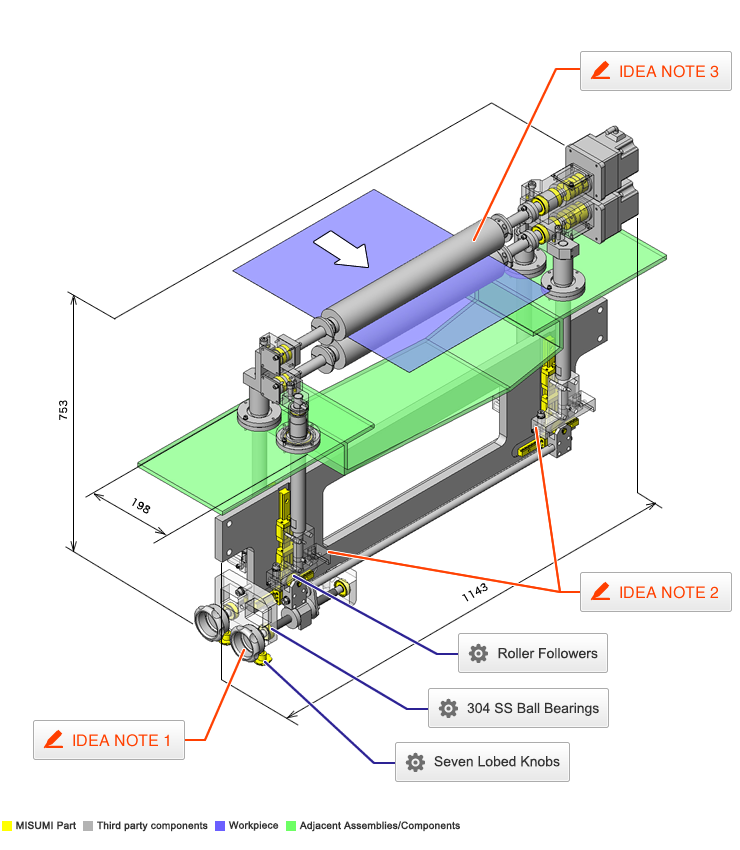
No.000225 Roller Cleaning Mechanism
48
Glass substrate cleaning using a set of rollers
Related Category


304 SS Ball Bearings
| Product name | EN 1.4301 Equiv. Ball Bearings |
|---|---|
| Part number | SUB6202ZZ |
Selection criteria
High water resistance against such liquid as cleaning solutions.
Available sizes
■Ball Bearings for EN 1.4301 Equiv.
| Component | Material |
|---|---|
| Inner and Outer Ring Shield Retainer Ball | EN 1.4301 Equiv. |
■Sizes and Dimensions
| I.D. | O.D. | Thickness |
|---|---|---|
| 6 | 19 | 6 |
| 8 | 22 | 7 |
| 24 | 8 | |
| 10 | 26 | |
| 30 | 9 | |
| 12 | 28 | 8 |
| 32 | 10 | |
| 15 | 9 | |
| 35 | 11 | |
| 17 | 10 | |
| 40 | 12 | |
| 20 | 42 | |
| 47 | 14 |
Accuracy Info
■Accuracy of Ball Bearings for EN 1.4301 Equiv.
| I.D. | Tolerance | O.D. | Tolerance | Thickness | Tolerance |
|---|---|---|---|---|---|
| 6 | +0.05 0 | 19 | 0 - 0.03 | 6 | 0 -0.12 |
| 8 | 22 | 7 | |||
| 24 | 8 | ||||
| 10 | 26 | ||||
| 30 | 9 | ||||
| 12 | 28 | 8 | |||
| 32 | 0 - 0.035 | 10 | |||
| 15 | 9 | ||||
| 35 | 11 | ||||
| 17 | 10 | ||||
| 40 | 12 | ||||
| 20 | 42 | ||||
| 47 | 14 |
Performance info.
■Load Information of Ball Bearings for Special Environment - EN 1.4301 Equiv.
| I.D. | O.D. | Thickness | Basic Load Rating | Allowable Rotational Speed | |
|---|---|---|---|---|---|
| Cr (Dynamic) N | Cr (Static) N | rpm | |||
| 6 | 19 | 6 | 52 | 32 | 2100 |
| 8 | 22 | 7 | 66 | 41 | 2000 |
| 24 | 8 | 67 | 42 | 1900 | |
| 10 | 26 | 91 | 59 | 1800 | |
| 30 | 9 | 102 | 72 | 1500 | |
| 12 | 28 | 8 | |||
| 32 | 10 | 136 | 92 | ||
| 15 | 9 | 112 | 85 | 1300 | |
| 35 | 11 | 153 | 113 | ||
| 17 | 10 | 120 | 98 | 1200 | |
| 40 | 12 | 192 | 144 | 1100 | |
| 20 | 42 | 188 | 152 | 1000 | |
| 47 | 14 | 256 | 200 | 900 | |

Seven Lobed Knobs
| Product name | Plastic Knobs/Seven Lobed Knobs |
|---|---|
| Part number | NKSM8-40 |
Selection criteria
Select this product which is suited in manual works for stopper to maintain the height after adjustment.
Available sizes
■Seven Lobed Knobs
| Screw | Knob | Screw | |
|---|---|---|---|
| Material | Material | Surface Treatment | |
| Threaded | Nylon 6 (Mat Black) | JIS-SWCH10R | Trivalent chromate |
| Tapped | Brass (Insert) | - | |
■Sizes and Dimensions
| Thread Dia. | Thread Length | Thread Depth | External Shape | |||||||||
|---|---|---|---|---|---|---|---|---|---|---|---|---|
| 10 | 15 | 16 | 20 | 25 | 30 | 40 | 45 | 50 | 55 | |||
| 5 | ○ | ○ | - | ○ | ○ | ○ | - | - | - | - | 9.5 | 25 |
| 6 | ○ | - | ○ | ○ | ○ | ○ | - | - | - | - | 12 | 32 |
| 8 | - | - | ○ | ○ | ○ | ○ | ○ | - | - | - | 14 | 40 |
| 10 | - | - | - | - | ○ | ○ | ○ | ○ | - | ○ | 18 | 50 |
| 12 | - | - | - | - | - | ○ | ○ | - | ○ | - | 22 | 63 |

Roller Followers

| Product name | Roller Followers/Separate/Flat Type |
|---|---|
| Part number | NASTFZ10 |
Selection criteria
Suitable for converting the linear motion of feed screws to up and down motion via cams.
Available sizes
■Roller Followers
| Grease | No Seal | With Seal | Material | ||
|---|---|---|---|---|---|
| Crowned | Flat Type | Crowned | Flat Type | ||
| General | ○ | ○ | ○ | ○ | EN 1.3505 Equiv. |
| - | ○ | ○ | ○ | EN 1.4125 Equiv. | |
| Low Rebound | - | - | - | ○ | |
■Sizes and Dimensions
| O.D. (mm) | I.D. (mm) | Thickness (mm) | |
|---|---|---|---|
| No Seal | With Seal | ||
| 19 | 6 | 9.8 | 13.8 |
| 24 | 8 | ||
| 30 | 10 | 11.8 | 15.8 |
| 32 | 12 | ||
| 35 | 15 | ||
| 40 | 17 | 15.8 | 19.8 |
| 47 | 20 | ||
Accuracy Info
■Accuracy Information of Roller Followers
Shaft Dia. Tolerance: 0
-0.008(mm).
Roller Dia. Tolerance: 0
-0.005(mm).
Performance info.
■Speeds・Loads (Load info.) of roller followers
| I.D. -O.D. | Basic Dynamic Load Rating C(kN) | Basic Static Load Rating Cor(kN) | Max. Allowable Load (kN) | Track Load Capacity (kN) | Max. Rotational Speed (rpm) | ||||
|---|---|---|---|---|---|---|---|---|---|
| No Seal | With Seal | ||||||||
| Crowned | Flat Type | Crowned | Flat Type | No Seal | With Seal | ||||
| Ø6-Ø19 | 4.12 | 4.55 | 0.36 | 1.37 | 3.53 | 1.37 | 3.53 | 20000 | 8000 |
| Ø8-Ø24 | 5.68 | 5.89 | 0.78 | 1.86 | 4.02 | 1.86 | 4.51 | 17000 | 6800 |
| Ø10-Ø30 | 9.7 | 9.67 | 1.42 | 2.45 | 5.59 | 2.45 | 6.86 | 15000 | 6000 |
| Ø12-Ø32 | 10.4 | 10.9 | 2.11 | 2.74 | 5.98 | 2.74 | 7.35 | 13000 | 5200 |
| Ø15-Ø35 | 12.3 | 14.3 | 4.73 | 3.14 | - | - | 8.04 | 10000 | 4000 |
| Ø17-Ø40 | 17.4 | 20.9 | 5.81 | 3.72 | 11.8 | 9500 | 3800 | ||
| Ø20-Ø47 | 19.2 | 24.5 | 4.61 | 13.8 | 8500 | 3400 | |||


IDEA NOTE Simplifying brush replacement
The brush section is designed with a mechanism to be removed together with the shaft in order to simplify brush replacement.

1. Remove the mounting screws of parts No. 218 and 220, and slide No. 220 to left to pull the right end from part No. 218.

2. Remove all the parts that are installed on part No. 226. The bearing, oil seal and collar are to be pulled out to the left side.

3. This enables part No. 220 to be tilted, allowing its left end to be pulled from part No. 226 by moving it to the right (motor) using a small clearance.

-
 Terms of use of CAD data and simplified drawing data
- These terms and conditions (hereinafter referred to as “the Terms") set forth the conditions for downloading CAD data and simplified drawing data provided by MISUMI Corporation (hereinafter referred to as "MISUMI") via www.misumi-europe.com operated by MISUMI Europa GmbH(hereinafter referred to as the "Website"). By downloading CAD data and simplified drawing data posted on the Website (hereafter referred to as “Data”), customers are deemed to have agreed to these Terms.
- 1. Purpose of Use
-
MISUMI offers the following:
1)CAD data found on the Website (3D CAD data, 3D Intermediate data and 2D CAD data) for the purpose of informing customers of the characteristics of the products offered by MISUMI or a manufacturer affiliated with MISUMI for use in their designs.
2)Simplified drawing data (in PDF format) for the purpose of checking the specifications of products. - 2. Characteristics of Data
- There may be a discrepancy in certain characteristics of products (for example: tolerance, surface roughness, chamfer, etc.) between the Data and the actual product. Furthermore, for the purpose of reducing the file size of the Data, some information such as oil groove shapes, threads, or spring shapes, may be removed from the Data.
- 3. Disclaimer
- MISUMI carefully creates the Data but makes no warranty as to the quality, accuracy, functionality, safety, reliability, etc., of the Data. MISUMI may at any time, and with no prior notice to customers, revise or delete Data. MISUMI assumes no responsibility for any damage or loss resulting from any revision or deletion of the Data, or any errors in said data. Customers are solely responsible for all aspects of their own designs, including those made using the Data. MISUMI may provide customers with design example data on the Website, but the quality, accuracy, functionality, safety, reliability, etc., of such data are not guaranteed. MISUMI may, at any time, and in its sole discretion, request that the customer cease its use of or destroy the Data in its possession. MISUMI may request the customer provide MISUMI documentation of such destruction.
- 4.Prohibited Acts
-
Customers or users of the Data, are prohibited from the following acts regarding the Data, in whole or in part:
(1)Requesting quotations or placing orders for products with third parties other than those authorized by MISUMI or its affiliates;
(2)Receiving quotations or orders for products from third parties by providing the Data to a third party or using the Data in their own business;
(3)Displaying links to the Website related to the Data on their own websites, etc., without consent of MISUMI or its affiliates;
(4)Using or reproducing the Data beyond the scope of the above-stated Purpose of Use;
(5)Modifying, altering, tampering with, translating, or adapting the Data;
(6)Selling, transferring, lending, sublicensing, or providing the Data to third parties in any way without consent of MISUMI or its affiliates;
(7)Altering the content, reverse engineering, decompiling, disassembling, or analyzing the Data;
(8)Publicly disclosing or exhibiting the Data without consent of MISUMI or its affiliates;
(9)Using the Data for the purpose of providing products and services identical or similar to those of MISUMI or its affiliates;
(10)Performing acts that interfere with the proper functioning of this Website, such as acquiring Data in bulk. - 5. Copyright
-
All title and copyright in and to any information contained in the Data are owned by MISUMI or the relevant manufacturer affiliated with MISUMI and are protected by applicable copyright laws and international treaties. By downloading Data, the customer acquires no ownership rights of any kind in the intellectual property contained within. Without prior approval from MISUMI, no part of the Data may be utilized (reproduced, modified, reverse-engineered, uploaded, presented, sent, distributed, licensed, sold, or published) for any purpose other than that mentioned above.
In the event Data is found to have been to be used for any purpose other than that mentioned above or against any applicable laws or the Terms, MISUMI may pursue any legal remedy available to it, which may result in forbidding the offending user from using the Data or accessing the Website. - 6. Third-Party Data
- MISUMI offers some Data provided by third parties. Such Data may be subject to separate terms and conditions, in addition to these terms. MISUMI makes no guarantee or warranty regarding Data from third parties.
- 7. Export Control
- Customers shall comply with all applicable laws and regulations regarding the export of the Data.
- 8. Amendments to the Terms
- MISUMI may, at any time, and in its sole discretion, modify these terms and conditions; any such modification will be effective immediately.
- 9. Severability
- If any term or provision of these Terms is invalid, illegal, or unenforceable in any jurisdiction, such invalidity, illegality, or unenforceability shall not affect any other term or provision of these Terms or invalidate or render unenforceable such term or provision in any other jurisdiction. Section 139 BGB (German Civil Code) shall not apply.
- 10.Miscellaneous
-
In the event that Customers violate the Terms, MISUMI and/or MISUMI Europa GmbH shall be entitled to claim the damages and expenses (including attorney's fees) incurred by such violation against the Customers.
These Terms and any disputes arising in connection therewith shall be exclusively governed by and construed in accordance with the laws of the Federal Republic of Germany, without regard to its conflicts of law principles. The courts located in Frankfurt am Main/Germany shall have exclusive jurisdiction to adjudicate any dispute arising in connection with these Terms. By downloading the Data, you agree to submit to the exclusive and personal jurisdiction of the courts located in Frankfurt am Main/Germany. - Revised: September 21, 2025
CAD Data Download (Unit Assembly)
CAD Data Download: File Format
Cautions on the CAD data
-
Assembly data shows the assembly drawings in the concept design phase. The sole purpose of the data is to explain the structure and functionality of the assembly and is not considered nor to be used as a final design.
You will need to edit the Data so that it meets your specific design conditions. -
The CAD data unit assembly consists of sub-assemblies.
Each sub-assembly unit can be used as it is or can be edited. - The Data for fabricated parts is based on easy-to-edit dimensions and shapes in sketches and histories.
- The Data including the third-part components are made by the Company.
* The part in the frame is a sub-assembly unit.
-

- * Unit assembly CAD data consists of some sub-assemblies.
Each sub-assembly unit can be used as it is or can be edited.
Application Overview
Purpose
- Circuit board cleaning unit (height adjustable).
Points for use
- For clean room environment.
- A cover is added to protect equipment from splashing of dirt and cleaning agent.
Target workpiece
- Glass circuit board: W 400 x D 500 x t 0.5mm
Design Specifications
Operating Conditions or Design Requirements
- Up and down adjustment stroke ±5mm
- External size: W 198 x D 1143 x H 753mm
Required Performance
- Load of section for up and down: P = 300N
Selection Criteria for Main Components
- Select the tilting angle of knob, screw and roller follower that are operable for up and down movement by turning the knob manually.
Design Evaluation
Verification of main components
- Required manual operation force and motor moment of inertia under operating conditions are verified.
- Condition values: Up and down section load P = 300N, tilting angle of roller follower section α = 6°, efficiency of M16 x 1.0 η = 0.08, lead of M16 x 1.0 L = 1, friction coefficient of linear guide μ = 0.003
- Force due to up and down section: Fs = P x sinα = 300 x sin6°= 300 x 0.1 = 30N
- Friction resistance force: Fa = μ x P = 0.003 x 300 = 0.9N
- Torque to turn knob: T = (FS + FA) x L/(2πη) = (30 + 0.9) x 1/(2π x 0.08) = 78N・mm
- The force required for turning knob manually is F = 78/40 = 2N≈0.2kg because of knob diameter: 40mm
- Selection of Motor.
- Permissible load inertia of moment of motor: JM = 10 x 10-4kg・m²
Other Design Consideration
- The height adjustment mechanism of brush cleaning is connected by a front/back side shaft.
- Motor splash cover is easily removable to be cleaned or replaced.
- A protective cover is separately installed for mechanical elements such as the linear guide during cleaning (omitted in example image).
Explore Similar Application Examples


Payment Method


On-Demand Manufacturing
Certificates


Copyright © MISUMI Corporation All Rights Reserved.