
- inCAD Library Home
- > No.000115 Chuck Mechanism
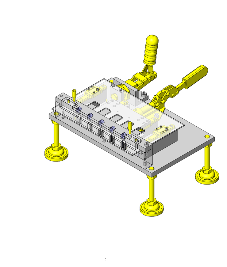
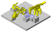
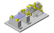
No.000115 Chuck Mechanism
26
Chuck mechanism capable of correcting positional displacement.
Related Category


Compact Cylinders
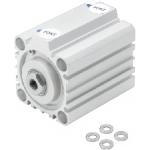
| Product name | Compact Cylinders |
|---|---|
| Part number | MSCCN16-10 |
Selection criteria
Used to switch between chucking and un-chucking.
Available sizes
■Compact Cylinders
| Tube I.D. | External Size | Rod Tip Screw | Stroke St | Body Length (+ St shown below) Rod | Rod Tip Length | ||||||||||||
|---|---|---|---|---|---|---|---|---|---|---|---|---|---|---|---|---|---|
| Screw Type | DIA.-Pitch | ||||||||||||||||
| 5 | 10 | 15 | 20 | 25 | 30 | 35 | 40 | 45 | 50 | 75 | 100 | ||||||
| Ø12 | □25 | Tapped | M3 x 0.5 | ○ | ○ | ○ | ○ | ○ | ○ | - | - | - | - | - | - | 22 | 3.5 |
| Ø16 | □29 | M4 x 0.7 | ○ | ○ | ○ | ○ | ○ | ○ | - | - | - | - | - | - | |||
| Ø20 | □36 | M5 x 0.8 | ○ | ○ | ○ | ○ | ○ | ○ | ○ | ○ | ○ | ○ | - | - | 29.5 | 4.5 | |
| Ø25 | □40 | M6 x 1.0 | ○ | ○ | ○ | ○ | ○ | ○ | ○ | ○ | ○ | ○ | - | - | 32.5 | 5 | |
| Ø32 | □45 | M8 x 1.25 | ○ | ○ | ○ | ○ | ○ | ○ | ○ | ○ | ○ | ○ | - | - | 33 | 7 | |
| Ø40 | □52 | ○ | ○ | ○ | ○ | ○ | ○ | ○ | ○ | ○ | ○ | ○ | ○ | 39.5 | |||
| Ø50 | □64 | M10 x 1.5 | - | ○ | ○ | ○ | ○ | ○ | ○ | ○ | ○ | ○ | ○ | ○ | 40.5 | 8 | |
| Ø63 | □77 | - | - | - | - | - | ○ | - | - | - | ○ | ○ | ○ | 46 | |||
| Ø12 | □25 | Threaded | M5 x 0.8 | - | ○ | - | ○ | - | ○ | - | - | - | - | - | - | 22 | 14 |
| Ø16 | □29 | M6 x 1.0 | - | ○ | - | ○ | - | ○ | - | - | - | - | - | - | 15.5 | ||
| Ø20 | □36 | M8 x 1.25 | - | ○ | - | - | - | ○ | - | - | - | ○ | - | - | 29.5 | 18.5 | |
| Ø25 | □40 | M10 x 1.25 | - | ○ | - | - | - | ○ | - | - | - | ○ | - | - | 32.5 | 22.5 | |
| Ø32 | □45 | M14 x 1.5 | - | ○ | - | - | - | ○ | - | - | - | ○ | - | - | 33 | 28.5 | |
| Ø40 | □52 | - | ○ | - | - | - | ○ | - | - | - | ○ | - | ○ | 39.5 | |||
| Ø50 | □64 | M18 x 1.5 | - | ○ | - | - | - | ○ | - | - | - | ○ | ○ | ○ | 40.5 | 33.5 | |
| Ø63 | □77 | - | - | - | - | - | ○ | - | - | - | ○ | ○ | ○ | 46 | |||
* Sensors are sold separately.
Selection Steps
■Selection procedure of compact cylinders (See "Technical Information" shown below for details.).
1.Define various conditions of the load.
↓
2.Calculate the cylinder output. (in case of double-acting type).
↓
3.Determine the tube I.D.
↓
4.Determine the theoretical reference speed.
↓
5.Verify the cylinder's cushion mechanism.
↓
6. Verify applicable lateral load on the cylinder
Performance info.
■Load Information of Compact Cylinders.
Min. Operating Pressure: 0.1 MPa.
Max. Operating Pressure: 1.0 MPa.
Theoretical Thrust (N):
| Tube I.D. | Operating Direction | Operating Pressure (MPa) | |
|---|---|---|---|
| 0.4 | 0.5 | ||
| Ø12 | Outstroke | 45 | 57 |
| Instroke | 34 | 42 | |
| Ø16 | Outstroke | 80 | 101 |
| Instroke | 60 | 75 | |
| Ø20 | Outstroke | 126 | 157 |
| Instroke | 94 | 118 | |
| Ø25 | Outstroke | 196 | 245 |
| Instroke | 151 | 189 | |
| Ø32 | Outstroke | 322 | 402 |
| Instroke | 241 | 302 | |
| Ø40 | Outstroke | 503 | 628 |
| Instroke | 422 | 528 | |
| Ø50 | Outstroke | 785 | 982 |
| Instroke | 660 | 825 | |
| Ø63 | Outstroke | 1247 | 1559 |
| Instroke | 1121 | 1402 | |

Sensors - For Cylinders

| Product name | Sensors for Cylinders |
|---|---|
| Part number | ME33L1 |
| Features | Sensors dedicated for Double Acting Cylinder |
Selection criteria
Detect chuck position.
Available sizes
■Sensors - For Cylinders, Grippers
| Load Voltage | Load Current | Sensor Type | Line | Wire Exit | Lead wire Length |
|---|---|---|---|---|---|
| DC24V AC110V | DC24V 5 ~ 40mA AC110V 5 ~ 20mA | Contact Point | 2-Line | Rear | 1m ・ 3m |
| 28VDC or Less | 0.1 ~ 40mA | No Contact | 3-Line | ||
| DC10 ~ 28V | 5 ~ 20mA | No Contact | 2-Line | ||
| 28VDC or Less | 0.1 ~ 40mA | No Contact | 3-Line | Top | |
| DC10 ~ 28V | 5 ~ 20mA | No Contact | 2-Line |
* Please see the product pages for detailed specifications.
Performance info.
■Load Information of Sensors - For Cylinders, Grippers
| Insulation Resistance | 100 MΩ or more with 500 VDC (between case and cable) |
|---|---|
| Withstanding Voltage | 1 min. with 1500 VAC (between case and cable) |
| Impact Resistance | 294m/s2 |
| Vibration Resistance | Lateral Amplitude 1.5 mm, 10 - 55 Hz (one sweep / min, two hours in X, Y, and Z directions respectively) |
| Ambient Temperature | 0 - +60°C (Non-Freezing) |
| Protection | IP67 (IEC Standard), JIS0920 (Water Resistant Type) |


-

-
 Terms of use of CAD data and simplified drawing data
- These terms and conditions (hereinafter referred to as “the Terms") set forth the conditions for downloading CAD data and simplified drawing data provided by MISUMI Corporation (hereinafter referred to as "MISUMI") via www.misumi-europe.com operated by MISUMI Europa GmbH(hereinafter referred to as the "Website"). By downloading CAD data and simplified drawing data posted on the Website (hereafter referred to as “Data”), customers are deemed to have agreed to these Terms.
- 1. Purpose of Use
-
MISUMI offers the following:
1)CAD data found on the Website (3D CAD data, 3D Intermediate data and 2D CAD data) for the purpose of informing customers of the characteristics of the products offered by MISUMI or a manufacturer affiliated with MISUMI for use in their designs.
2)Simplified drawing data (in PDF format) for the purpose of checking the specifications of products. - 2. Characteristics of Data
- There may be a discrepancy in certain characteristics of products (for example: tolerance, surface roughness, chamfer, etc.) between the Data and the actual product. Furthermore, for the purpose of reducing the file size of the Data, some information such as oil groove shapes, threads, or spring shapes, may be removed from the Data.
- 3. Disclaimer
- MISUMI carefully creates the Data but makes no warranty as to the quality, accuracy, functionality, safety, reliability, etc., of the Data. MISUMI may at any time, and with no prior notice to customers, revise or delete Data. MISUMI assumes no responsibility for any damage or loss resulting from any revision or deletion of the Data, or any errors in said data. Customers are solely responsible for all aspects of their own designs, including those made using the Data. MISUMI may provide customers with design example data on the Website, but the quality, accuracy, functionality, safety, reliability, etc., of such data are not guaranteed. MISUMI may, at any time, and in its sole discretion, request that the customer cease its use of or destroy the Data in its possession. MISUMI may request the customer provide MISUMI documentation of such destruction.
- 4.Prohibited Acts
-
Customers or users of the Data, are prohibited from the following acts regarding the Data, in whole or in part:
(1)Requesting quotations or placing orders for products with third parties other than those authorized by MISUMI or its affiliates;
(2)Receiving quotations or orders for products from third parties by providing the Data to a third party or using the Data in their own business;
(3)Displaying links to the Website related to the Data on their own websites, etc., without consent of MISUMI or its affiliates;
(4)Using or reproducing the Data beyond the scope of the above-stated Purpose of Use;
(5)Modifying, altering, tampering with, translating, or adapting the Data;
(6)Selling, transferring, lending, sublicensing, or providing the Data to third parties in any way without consent of MISUMI or its affiliates;
(7)Altering the content, reverse engineering, decompiling, disassembling, or analyzing the Data;
(8)Publicly disclosing or exhibiting the Data without consent of MISUMI or its affiliates;
(9)Using the Data for the purpose of providing products and services identical or similar to those of MISUMI or its affiliates;
(10)Performing acts that interfere with the proper functioning of this Website, such as acquiring Data in bulk. - 5. Copyright
-
All title and copyright in and to any information contained in the Data are owned by MISUMI or the relevant manufacturer affiliated with MISUMI and are protected by applicable copyright laws and international treaties. By downloading Data, the customer acquires no ownership rights of any kind in the intellectual property contained within. Without prior approval from MISUMI, no part of the Data may be utilized (reproduced, modified, reverse-engineered, uploaded, presented, sent, distributed, licensed, sold, or published) for any purpose other than that mentioned above.
In the event Data is found to have been to be used for any purpose other than that mentioned above or against any applicable laws or the Terms, MISUMI may pursue any legal remedy available to it, which may result in forbidding the offending user from using the Data or accessing the Website. - 6. Third-Party Data
- MISUMI offers some Data provided by third parties. Such Data may be subject to separate terms and conditions, in addition to these terms. MISUMI makes no guarantee or warranty regarding Data from third parties.
- 7. Export Control
- Customers shall comply with all applicable laws and regulations regarding the export of the Data.
- 8. Amendments to the Terms
- MISUMI may, at any time, and in its sole discretion, modify these terms and conditions; any such modification will be effective immediately.
- 9. Severability
- If any term or provision of these Terms is invalid, illegal, or unenforceable in any jurisdiction, such invalidity, illegality, or unenforceability shall not affect any other term or provision of these Terms or invalidate or render unenforceable such term or provision in any other jurisdiction. Section 139 BGB (German Civil Code) shall not apply.
- 10.Miscellaneous
-
In the event that Customers violate the Terms, MISUMI and/or MISUMI Europa GmbH shall be entitled to claim the damages and expenses (including attorney's fees) incurred by such violation against the Customers.
These Terms and any disputes arising in connection therewith shall be exclusively governed by and construed in accordance with the laws of the Federal Republic of Germany, without regard to its conflicts of law principles. The courts located in Frankfurt am Main/Germany shall have exclusive jurisdiction to adjudicate any dispute arising in connection with these Terms. By downloading the Data, you agree to submit to the exclusive and personal jurisdiction of the courts located in Frankfurt am Main/Germany. - Revised: September 21, 2025
CAD Data Download (Unit Assembly)
CAD Data Download: File Format
Cautions on the CAD data
-
Assembly data shows the assembly drawings in the concept design phase. The sole purpose of the data is to explain the structure and functionality of the assembly and is not considered nor to be used as a final design.
You will need to edit the Data so that it meets your specific design conditions. -
The CAD data unit assembly consists of sub-assemblies.
Each sub-assembly unit can be used as it is or can be edited. - The Data for fabricated parts is based on easy-to-edit dimensions and shapes in sketches and histories.
- The Data including the third-part components are made by the Company.
* The part in the frame is a sub-assembly unit.
-

- * Unit assembly CAD data consists of some sub-assemblies.
Each sub-assembly unit can be used as it is or can be edited.
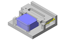
Application Overview
Purpose
- Chuck workpieces while correcting fine displacement.
- Springs are used to generate the necessary holding force. The claws of the chuck are adjustable to account for positional displacement.
Points for use
- Low precision workpiece chucking.
Target workpiece
- Shape: resin pin.
size: Ø10 x 45mm.
weight: 0.1kg.
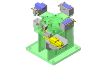
Design Specifications
Operating Conditions or Design Requirements
- Assumed workpiece displacement amount: ±1.5mm.
- Spring gripping force: 23.1 to 54.6N.
- Outer dimensions: W86 x D117.5 x H58mm.
Selection Criteria for Main Components
- Springs that produce a gripping force of 2kg during chucking are selected.
Design Evaluation
Verification of main components
- Spring gripping force is verified below.
- Confirmation of gripping force of chucks.
- Conditional value: spring constant k = 10.5N/mm.
Spring free length: L0 = 15mm.
Minimum spring length caused by maximum displacement amount 1.5mm: L1 = 9.8mm.
Spring length when displacement amount is 0mm: L2 = 11.4mm.
Maximum spring length caused by maximum displacement amount 1.5 mm: L3 = 12.8mm.
- Maximum spring deflection amount caused by maximum displacement amount 1.5mm: X1 = L0 - L1 = 5.2mm.
Spring deflection amount when displacement amount is 0mm: X2 = 3.6mm.
Minimum spring deflection amount caused by maximum displacement amount 1.5mm: X3 = L0 - L3 = 2.2mm.
- Maximum chuck gripping force: F1 = k x X1 = 10.5 x 5.2 = 54.6N.
Chuck gripping force when there is no workpiece displacement: F2 = k x X2 = 10.5 x 3.6 = 37.8N.
Minimum chuck gripping force: F3 = k x X3 = 10.5 x 2.2 = 23.1N.
- Conditional value: spring constant k = 10.5N/mm.
Other Design Consideration
- The cam shape applies load to the spring during chucking and completely opens the claws from the workpiece during un-chucking.
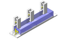
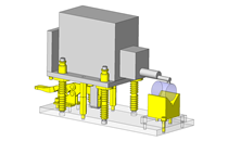
Explore Similar Application Examples


Payment Method


On-Demand Manufacturing
Certificates


Copyright © MISUMI Corporation All Rights Reserved.